Circuit design software for breadboards, boards and beyond
Design a circuit the way you would build it: on a breadboard, with real parts at real size. Simscuit checks the wiring as you go, simulates the circuit, and carries the same design on into a printed circuit board and a 3D-printed enclosure.
Design on a breadboard you already understand
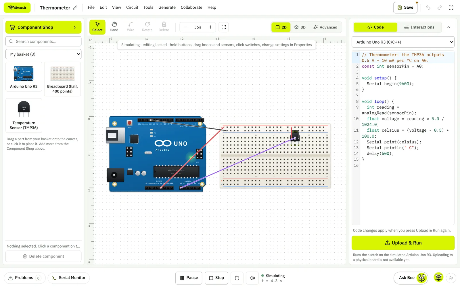
Parts sit on the 0.1 inch grid with their real pinouts, so what you draw is what you can build on the bench. Wires snap to pins with a click, the canvas zooms and pans like a design tool, and every part has properties you can change, from a resistor’s value to an LED’s colour.
Checks that catch mistakes early
- Design-rule checks for shorts, missing resistors, missing ground and over-current
- Simulation checks that report parts pushed past their datasheet ratings
- A Problems panel that names the part, the pin and the number that is wrong
From breadboard to manufacturing files
The same circuit opens in PCB Design Studio as a two-layer board, and its board outline can be wrapped in an enclosure in the 3D Design Studio.
Exports
- A circuit report
- A bill of materials
- A prompt that describes the circuit for an AI assistant
- Gerber, drill, BOM and placement files from the PCB
- STL, 3MF and OpenSCAD from the 3D design
Start from a template or a ready circuit
Templates cover LED Blink, a button-controlled LED, a traffic light, a potentiometer dimmer, a servo sweep, a doorbell, an RGB colour mixer, a night light, a thermometer, a seven-segment counter, a melody and a battery torch. Preassembled circuits add complete sensor and automation projects you can insert into your own design.
Questions
Does Simscuit draw schematics?
You design on a breadboard view, and the PCB studio derives the connections from the circuit. A separate schematic editor is not part of Simscuit today.
Can I share a design?
Yes. Projects can be exported, and organisations can share projects with their members.