How to design and simulate an electronic circuit online
This guide builds one small circuit properly: an LED with a current-limiting resistor and a push button on a breadboard, powered from an Arduino Uno’s 5 V pin. You will work out the resistor with Ohm’s law, check it in the simulator, then hand the LED to the Arduino and make it blink. It takes about twenty minutes and needs nothing but a browser.
What you will build
The same parts and wiring work on a real bench, so the circuit you simulate is the one you could build tomorrow.
- An Arduino Uno, used first as a 5 V supply and then as the controller
- A half-size breadboard
- A red 5 mm LED
- One resistor, whose value we calculate below
- A push button and a few jumper wires
How a breadboard is connected
On a standard breadboard each numbered row is split into two groups of five holes, a to e and f to j, and the five holes in a group are joined underneath. The channel down the middle separates the two groups, which is why chips sit across it. The long rails along the edges, marked + and −, run the length of the board and carry power; on some full-size boards the rails are broken halfway, so check before relying on them.
Two legs in the same group of five are connected. Two legs in different rows are not, unless a wire or a part joins them. Most first-circuit mistakes are a leg one row out.
Work out the resistor with Ohm’s law
An LED is a diode: once it conducts, the voltage across it stays close to its forward voltage whatever the current, so it cannot limit its own current. The resistor does that. The supply voltage minus the LED’s forward voltage is left across the resistor, and Ohm’s law turns that into a resistance.
For a red LED the forward voltage is about 2.0 V (check your LED’s datasheet: red is usually 1.8 to 2.2 V, blue and white about 3.0 to 3.3 V). Aim for 10 mA, bright enough and well inside a typical 20 mA rating. Then R = (5 V − 2.0 V) ÷ 0.010 A = 300 Ω. The nearest standard value above it is 330 Ω, which gives (5 − 2.0) ÷ 330 = 9.1 mA. The resistor dissipates 3.0 V × 9.1 mA = 27 mW, far below the 250 mW of a common quarter-watt resistor.
A 220 Ω resistor, which many kits include, gives about 13.6 mA: also fine. Leaving the resistor out is not, because the current is then set only by the LED and the supply, and the LED is overloaded.
| LED colour | Typical forward voltage | Exact resistor | Standard value | Resulting current |
|---|---|---|---|---|
| Red | 2.0 V | 300 Ω | 330 Ω | 9.1 mA |
| Yellow or green (standard) | 2.1 V | 290 Ω | 330 Ω | 8.8 mA |
| Blue or white | 3.2 V | 180 Ω | 180 Ω | 10 mA |
Build it in the simulator
With the button held, the simulator should show about 3 V across the resistor and about 9 mA through it, matching the sum above. If it does not, a leg is in the wrong row. View, Current Flow shows current as moving dots, and View, Voltage Colours shades each wire by its voltage, which makes a missing connection obvious.
- Create a free Simscuit account and start a new project in Circuit Studio (File, New Project). Add an Arduino Uno from the Component Shop if the project does not have one.
- Open the Component Shop and add a half breadboard, a red LED, a resistor and a push button.
- Place the LED across two rows. Its longer leg, the anode, goes towards the supply; the shorter leg, the cathode, beside the flat on its rim, goes towards ground.
- Select the resistor and set it to 330 Ω. Put one end in the LED’s cathode row and the other on the ground rail.
- Place the push button across the centre channel, so its two sides are in different rows.
- Wire the Uno’s 5V pin to one side of the button, the other side of the button to the LED’s anode row, and a GND pin to the ground rail. A wire end snaps to a pin when it is highlighted.
- Press Run Simulation. Hold the button: the LED lights. Hover over the resistor or a wire to read its voltage and current.
See what goes wrong without the resistor
Stop the simulation, replace the resistor with a wire and run it again. The LED’s current now goes far past the rating in its record: it glows, smokes and burns out, and the Problems list gives the current it reached and the limit it broke. Simscuit judges damage only against limits recorded in each part’s data, so the lesson is real arithmetic, not a guess. Undo, put the resistor back and the circuit works again.
Hand the LED to the Arduino and blink it
The resistor stays. An Arduino output pin is a 5 V source with some internal resistance, not a current limiter, and the Uno’s ATmega328P should not be asked for more than about 20 mA per pin. At 9 mA this LED is comfortably inside that.
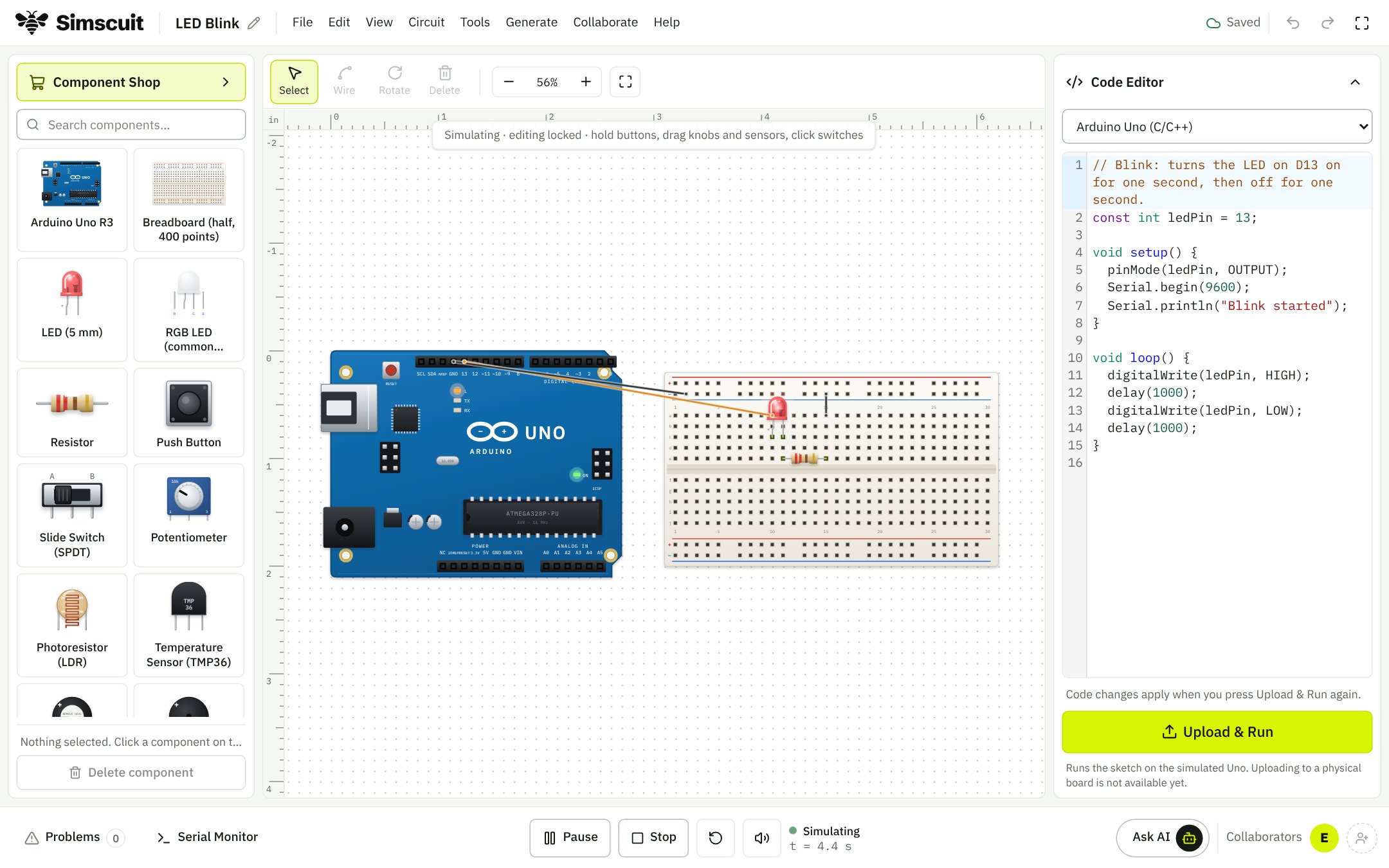
- Remove the button and its wires. Wire the LED’s anode row to the Uno’s D13 pin instead of 5V.
- Open the code editor (View, Show Code Editor) and type the sketch below.
- Press Run Simulation. The LED turns on for one second and off for one second.
- Change both delays to 200 and run it again. Change one to 100 and the other to 900: the LED flashes briefly once a second.
// Blink an LED on pin 13: one second on, one second off.
const int ledPin = 13;

void setup() {
  pinMode(ledPin, OUTPUT);   // pin 13 drives the LED
}

void loop() {
  digitalWrite(ledPin, HIGH); // 5 V on the pin: the LED lights
  delay(1000);                // wait 1000 ms
  digitalWrite(ledPin, LOW);  // 0 V: the LED goes out
  delay(1000);
}
Check the design before you build it
- Every LED has its own resistor (sharing one between LEDs in parallel makes them unequal).
- Every part that needs ground is connected to the board’s GND.
- No output pin drives more than its rated current; the simulator warns when one does.
- The design rule checks are clear: Simscuit flags shorts, over-current and missing resistors.
- Export a bill of materials (File, Export, BOM) so you buy exactly what you simulated.
Where to go next
Add a second LED on another pin and make a traffic light, read the button from code, or turn the circuit into a printed circuit board.
Questions
What resistor do I need for an LED on 5 V?
For a red LED at about 10 mA, (5 − 2.0) ÷ 0.010 = 300 Ω, so use 330 Ω. 220 Ω (about 14 mA) is also safe for most 5 mm LEDs.
Can I simulate a circuit without an Arduino?
Yes. Simscuit simulates battery circuits with no board and no code; the Battery Torch template is a 9 V battery, a button, a 1 kΩ resistor and a blue LED.